Page 1 of 4
BMW Engined Aquilla
Posted: Thu Mar 04, 2010 10:41 am
by Oddball
Here are a few pics of a conversion of an Aquilla to fit a BMW engine to it. The wiring is fairly complex as there are two batteries. I have based the circuit on a so called 'Z' diagram by Bob Nuckolls of the Aeroelectric Connection. Its a well thought out diagram that is failure tolerant- that is, any one failure should not cause an emergency landing.
Re: BMW Engined Aquilla
Posted: Thu Mar 04, 2010 10:51 am
by Oddball
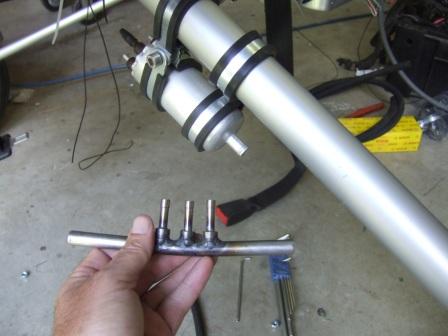
Here are some more pics of the fuel system; there are two pumps that feed from either side of the fuel manifold. The manifold allows the integration of the three tank outlets, about 6mm in diameter, to the pump inlets, of a larger diameter.
The pipes to the fuel pumps had to be integrated with aluminium pipe to allow for smaller bend radii (see photo Fuel5).
Fuel8 shows the relay that controls the starting of the main fuel pump- controlled by the E-Boxi; the standby/ backup pump comes on immediately when you switch over to the backup ECU.
Re: BMW Engined Aquilla
Posted: Thu Mar 04, 2010 11:05 am
by Oddball
Here is the wiring system and some more of the components. The first is the E-Boxi mounting point; the circled item is the alternator contactor. Each battery and the alternator may be isolated from the system by using these contactors.

- E_mount1.JPG (34.38 KiB) Viewed 6759 times
Here is a general shot of the engine

- Engine1.JPG (32.41 KiB) Viewed 6760 times
Another general shot showing the RDAC and IO Extender mounting on the left and the fuel pressure regulator on the right.

- Engine2.JPG (34.71 KiB) Viewed 6759 times
This is the FAP- the Fuse Annunciator Panel; it gives you the status of all the fuses by pressing a button; a dead LED indicates a blown fuse and the panel will eventually be engraved with the location of the fuse.

- FAP1.JPG (21.95 KiB) Viewed 6759 times
Here is the backup HT coil mounting; this supplies the second plugs with power- the first ones use a coil on plug arrangement, as seen in the second photo

- Plug1.JPG (28.81 KiB) Viewed 6759 times

- Plug2.JPG (25.78 KiB) Viewed 6759 times
This is the panel- a bit funny looking as it is not screwed in yet

- Pod1.JPG (20.99 KiB) Viewed 6759 times
Here is one of the throttle bodies; the cork seen on the right is to close the second injector hole as we are waiting for parts. The engine ran just fine like this although it tends to spit the cork out as you switch off sometimes!

- Throttlebody1.JPG (33.72 KiB) Viewed 6759 times
Re: BMW Engined Aquilla
Posted: Thu Mar 04, 2010 11:11 am
by Oddball
Re: BMW Engined Aquilla
Posted: Thu Mar 04, 2010 12:12 pm
by ystervark7
Congratulations Jay!!
(Jay is very modest but he did manage to get the BMW going by himself without too many problems.)
Re: BMW Engined Aquilla
Posted: Thu Mar 04, 2010 2:43 pm
by Cloud Warrior
I'll wait for the wireless version to come out............
Re: BMW Engined Aquilla
Posted: Thu Mar 04, 2010 9:10 pm
by JACO
Re: BMW Engined Aquilla
Posted: Thu Mar 04, 2010 10:55 pm
by Oupa-G
Nice alternative thinking just the right stuff for cross-pollination
Cheers Oupa-G
Re: BMW Engined Aquilla
Posted: Fri Mar 05, 2010 1:39 pm
by caneco
very nice setting,wen its ready to fly?
Re: BMW Engined Aquilla
Posted: Fri Mar 05, 2010 4:13 pm
by Kalahari
Well done!
From the attached photo it seem as if someone's mother in law paid you a visit at the hangar!
Re: BMW Engined Aquilla
Posted: Mon Mar 08, 2010 9:12 am
by Oddball
We should be able to fly it in a couple of weeks now; just moving the oil cooler to a position that provides it with more airflow. I'll post pictures, sans broom

later.
Re: BMW Engined Aquilla
Posted: Mon Mar 08, 2010 2:59 pm
by Tailspin
Jay
This really looks Good.
Nice going Dude - would like to take a closer look at the wiring specifically, thinking going that way for the Next project.
Re: BMW Engined Aquilla
Posted: Thu Mar 11, 2010 4:33 pm
by Oddball
Some more photos as promised...
The oil cooler has been situated in the stock (BMW) position, which is completely wrong for this application.

- OilCoolerOrig.JPG (30.87 KiB) Viewed 6441 times
I have moved it below the engine to a position where it will enjoy more airflow, which has entailed some plumbing modification of course.

- Oil_new1.JPG (31.12 KiB) Viewed 6441 times

- Oil_new2.JPG (34.08 KiB) Viewed 6441 times
The arrow is showing a fan that I used to blow away the exhaust fumes generated (small arrows) when I was running the engine- it gets a bit uncomfortable in the workshop otherwise!

- Oil_new3.JPG (32.51 KiB) Viewed 6441 times
We used these new plumbing arrangments to add some sensors, for which I made some custom housings

- SensorHousing1.JPG (16.39 KiB) Viewed 6441 times
These have been used for oil pressure (single arrow) and oil temp (double arrow)

- Oil_new4.JPG (29.92 KiB) Viewed 6441 times
We have put oil temperature measurements on both sides of the cooler so that we can monitor how the cooler is working. I recall a story on a replica Spitfire that was built using a Jaguar engine where they had huge cooling problems with the engine- they eventually figured out that most of the radiator had been virtually blanked off so that there was no cooling from the radiator at all. These sensors should help us to figure that problem out should we have cooling issues.
Re: BMW Engined Aquilla
Posted: Thu Mar 11, 2010 4:46 pm
by Wargames
What is the reason for the three into two arrangement on the fuel manifold??
Re: BMW Engined Aquilla
Posted: Thu Mar 11, 2010 5:41 pm
by Oddball