

I have recently purchased a regulator recitifier to install on my plane. To date i have only had a digital instument pod, running directly off my motor (rotax 503, inverted, single ignition).
The wiring diagram for the regulator/rectifier gives two installation options:
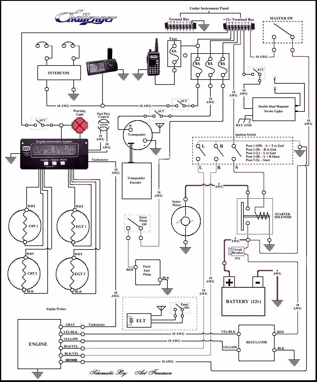
1) Motor to regulator then on to the electrical toys eg instruments, strobes etc
2) Motor to regulator, then to battery, then on to the instruments, strobes etc
For both otions it simply indicates to ground the elctrical item.
My questions to the electrical fundies are:
1) Are there any benefits of either installation option (ie with/without a battery in the circuit).
2) Will the regulator/rectifier and/or battery provide some filtering of the interference in the I/C
3) There must be a limit as to how many toys can be installed. I want to power my digital instruments, a nose spot light, a strobe or two and also have a plug or two for additional items at a later stage eg GPS (and also an in line electrical fuel pump in the near future)..... is this too much power drawn through the reg/rec:?: ......
4) What diameter/type of electrical wire is suitable as i can do without an in flight fire caused by overheating of overloaded wires.
5) Is it preferable to earth all the electrics to one single point on the airframe and/or the negative battery terminal (if installed)
Hoping someone has the know-how to give some advice is i would like to get it right the first time around.
FLY SAFE!!!!!!!!!


